Introduction
Welcome to the Network-of-Things Applications (NoT A) Lab.
This lab will guide you through the components used to connect devices to the internet and will give you a hands-on experience using actual hardware and software as well as realistic network topologies.
We will cover topics like software development on ressource-constrained embedded devices, network protocols used in the IoT, local data processing in a so-called fog zone and cloud-based data processing.
But before we dive right in we will have to cover some basics to get you started.
As a first task click on the arrow to the right to get to the first chapter.
Basics
Congratulations for finishing the first task! Yor ability to follow basic instructions will come in handy later on.
In the course of this lab we will be using a lot of commandline programs without a graphical user interface. If you are not used to using a liux commandline or want a quick refresher the next sub-chapter will give you a brief introduction.
If you feel like a real hacker already
you may also skip the next sub-chapter and go straight
to working with NodeMCU
and come back whenever you see fit.
Linux commandline basics
Before we start our adventure to the depths of textual programs we have to open a terminal emulator as shown in the video below.
Navigation
The commands you execute on the commandline always work relative to a directory on the filesystem. This directory is called the working directory and you can find out your current working directory by typing
pwd
on the commandline and hitting enter.
After hitting enter your terminal should show something like the following:
[user@computer ~]$ pwd
/home/user
This means that you are currently working in the
/home/user directory.
Often times $ pwd (for “print working directory”) is used as an abbreviation to saying
“Type pwd into a terminal emulator and hit the enter key”,
the $ prefix stems from the way the terminal displays
things, you should not type it in when asked to execute a program.
To demonstrate navigating the filesystem we first
have to create some directories to navigate to.
Execute the following commands to create the directories
test_1 and test_2:
$ mkdir test_1
$ mkdir test_2
Now type $ ls (for “list”) to see the content of the current
working directory. You should see, possibly among others,
your newly created test folders.
[user@computer ~]$ ls
test_1
test_2
To change your current working directory you use
the cd command:
[user@computer ~]$ pwd
/home/user
[user@computer ~]$ cd test_1
[user@computer ~/test_1]$ pwd
/home/user/test_1
To go up in the directory structure you can use
.. in a path.
[user@computer ~/test_1]$ pwd
/home/user/test_1
[user@computer ~/test_1]$ cd ..
/home/user
[user@computer ~]$ cd test_2
[user@computer ~/test_2]$ pwd
/home/user/test_2
[user@computer ~/test_2]$ cd ../test_1
/home/user
[user@computer ~/test_1]$ pwd
/home/user/test_1
Tab completion
As typing is tedious you should, whenever possible, use the Tab ↹ key. When pressed once it will autocomplete whatever you entered as far as possible, when pressed twice it will show possible further completions. Try it by typing the following and pressing the tabulator key whenever a ↹ symbol comes up.
[user@computer ~/test_1]$ cd
[user@computer ~]$ cd te↹
(should autocomplete to test_)
[user@computer ~]$ cd test_↹↹
test_1/ test_2/
(should show options to go to)
To cancel the currently running program or to clear the current commandline you can use the key combination Ctrl+C (or Strg+C on a german keyboard). Pressing these two keys asks the running program to exit.
Reading and writing files
We will use a text editor to create a simple file.
The text editor we use is called nano.
To start it type the following:
[user@computer ~]$ cd
[user@computer ~]$ cd test_1
[user@computer ~/test_1]$ nano hello.txt
The last command starts an interactive text editor.
For now just type hello world! and use the key combination
Ctrl+X (Strg+X on a german keyboard) to exit the editor.
The editor will ask if it should save the changes you made.
Type Y (or J on a german system) and hit enter to save
the changes and exit the editor.
To read the content of the file we just created we can
either use nano to open it or the cat command to
print its content to the terminal.
[user@computer ~/test_1]$ cat hello.txt
hello world!
Hint: Be careful when cating files to the terminal,
sometimes when reading binary files instead of text files
your terminal may end up all garbled up.
Command history
In addition to using the Tab ↹ key for autocompletions you should also use the command history. The terminal automatically keeps a log of the last commands you executed and you can navigate these commands using the arrow keys ↑↓ on your keyboard.
You can also search the history using the key combination Ctrl+R (Strg+R on a german keyboard).
NodeMCU
In this lab we will be using a small microcontroller based development board to act as our internet connected device. These microcontrollers are most commonly programmed in low level programming languages like C or C++, we will instead by using an ESP8266 microcontroller running the NodeMCU firmware, this firmware lets us program the controller using the Lua programming language which allows for faster experimenting than C or C++.
Communication
Before we can program the controller we have to be able to communicate with it. To do so please disconnect the USB connection between your Raspberry Pi and the microcontroller board, count to two and reconnect it.
Now run $ dmesg in a terminal, one of the last lines
should read something like:
[100000.000000] usb 1-5: cp210x converter now attached to ttyUSB0
the last part is what we need, the device name we use
to communicate to the microcontroller.
If dmesg shows a different device name you should
use that instead of ttyUSB0 wherever it comes up.
Now we use picocom to connect to the controller,
see its output and send commands to it.
[user@computer ~]$ picocom -b 115200 /dev/ttyUSB0
picocom v3.1

[…]

Type [C-a] [C-h] to see available commands
Terminal ready
If you now press enter the controller should answer with
a > command prompt.
Type [C-a] [C-h] to see available commands
Terminal ready
>
To check if everything is working correctly we may now turn on an LED on the controller board using the following commands:
> gpio.mode(4, gpio.OUTPUT)
> gpio.write(4, gpio.LOW)
and turn it off again using this command:
> gpio.write(4, gpio.HIGH)
Hint: If no LED turned on and off there may be something wrong with your setup and you should seek assistance.
The controller board has an onboard LED connected between the supply voltage and pin 4 of the microcontroller. For more information on the commands you just executed consult the NodeMCU documentation.
Uploading code
Using the NodeMCU commandline for anything but basic commands quickly becomes tedious, so the next step is to upload full programs to the controller in one go.
To do so we first have to exit picocom.
Always remember to exit picocom before uploading a program.
Doing so can be a bit tricky as the process consists of two key combinations. You have to first press Ctrl+A and then Ctrl+X (Strg+A and then Strg+X on a german keyboard, respectively).
After you hit these key combinations picocom should exit with the output:
>
Terminating...
Thanks for using picocom
[user@computer ~]$
Before we can upload a project to the microcontroller we
need a project to upload, a basic template is located in
the /usr/src/nodemcu_base directory of your Raspberry Pis.
Copy this template to a new project directory using the following commands:
[user@computer ~]$ mkdir projects
[user@computer ~]$ cp -rv /usr/src/nodemcu_base projects/chapter_1
[user@computer ~]$ cd projects/chapter_1
The template contains three files init.lua credentials.lua
application.lua before going into any detail on what the
purpose of these files is we can just upload them as-is using
the following command (remember that you might have to replace the
ttyUSB0 part):
[user@computer ~]$ nodemcu-uploader --port /dev/ttyUSB0 upload *.lua
opening port /dev/ttyUSB0 with 115200 baud
Preparing esp for transfer.
Transferring init.lua as init.lua
Transferring credentials.lua as credentials.lua
Transferring application.lua as application.lua
All done!
[user@computer ~]$
Hint: If the command above throws any errors you should try pressing the reset button on the microcontroller board and quickly retry flashing after releasing it.
After uploading you can reconnect picocom, press the reset button on the microcontroller board and should see output like the following:
[user@computer ~]$ picocom -b 115200 /dev/ttyUSB0
…
init: WiFi credentials are not configured
init: startup will continue in 3s
> init: handing over to application
Hello from your NodeMCU application!
Hi from your NodeMCU application!
…
NodeMCU project structure
The template project is split into the files init.lua, credentials.lua and
application.lua, we will now take a look at these files in a text editor.
init.lua
This file is executed by the firmware on the microcontroller,
it is used to set up a WiFi connection and hand over to application.lua.
credentials.lua
This file contains name and password of the WiFi network to connect to.
application.lua
This file contains the application running on the microcontroller, most of your code goes in here.
Task: Read the code in application.lua and try editing the greeting_print
function so that the LED is turned on whenever the application prints
“Hello from your NodeMCU application!” and off whenever the application prints
“Hi from your NodeMCU application!”.
NodeMCU programming model
NodeMCU is inspired by node.js, a javascript framework and server based on the concept of callback-based asynchronous programming.
This concept can take some getting used to. The following examples should give you an idea of how asynchronous programs are structured.
Synchronous vs. Asynchronous
The previos chapter ended in an example of a blinking LED program. Some of you may have already used Arduino to write a similar program:
void setup() {
  pinMode(LED_BUILTIN, OUTPUT);
}

void loop() {
  digitalWrite(LED_BUILTIN, HIGH);
  delay(1000);
  digitalWrite(LED_BUILTIN, LOW);
  delay(1000);
}
The first thing to notice is that no other code
can run while the loop function is running.
This means that the microcontroller will
sit idly for one second while the delay(1000)
calls are being executed.
The code-snipped below shows the asynchronous counterpart to the Arduino code above.
function led_toggle()
   if (status == gpio.LOW) then
      status = gpio.HIGH
   else
      status = gpio.LOW
   end

   gpio.write(4, status)
end

function led_setup()
   gpio.mode(4, gpio.OUTPUT)

   -- schedule led_toggle() to run once a second
   tmr.create():alarm(1000, tmr.ALARM_AUTO, led_toggle)
end
The function led_toggle is scheduled to be executed
every 1000ms using the tmr.create():alarm() call.
In the meantime the microcontroller is free to run different
pieces of code.
Hint: The NodeMCU firmware makes use of this property,
for example for handling network connections.
This is why you should avoid writing functions
in NodeMCU that may take a long time to run,
especially by avoiding the tmr.delay() function.
Handling input
After learning the basics of what asynchronous programming means we have to learn how they transfer to actual real-world tasks.
One real-world task is acting upon data input.
Replace the content of you application.lua file
with the code-snippet below and upload it to your
microcontroller.
function uart_on_char(char)
   print("Read character: "..char.." from uart")
end

function uart_setup()
   -- Whenever 1 byte of data is received
   -- run uart_on_char, do not interpret the
   -- received byte as lua command
   uart.on("data", 1, uart_on_char, 0)
end

uart_setup()
After uploading the program, resetting your microcontroller and connecting to it using picocom the microcontroller should respond to every character you enter with a line like the following:
[user@computer ~]$ picocom -b 115200 /dev/ttyUSB0
Read character: h from uart
Read character: e from uart
Read character: l from uart
Read character: l from uart
Read character: o from uart
Task: modify the application.lua to turn
on the LED whenever the character l is received
and off whenever the character d is received.
Controlling RC servo motors
Controlling RC servos with a microcontroller is rather simple, due to the minimalistic communication protocol used by these motors.
The diagram below is a mostly complete description of this protocol:
5V  ┌────┬┄┄┄┄┐               ┌───
    │    │    ┆               │
0V ─┘    └────┴───────────────┘
    0ms  1ms  2ms             20ms
The angle the servo is set to is controlled by the pulse length seen in the diagram.
- A pulse length of 1ms means turn all the way in one direction
- A pulse length of 2ms means turn all the way in the other direction
- A pulse length of 1.5ms means move to the origin
To generate these pulses we will use the pwm module.
Below are two functions to controll the servos.
servo_setupperforms the necessary setup to control a servo motor on pin 2 of the microcontrollerservo_setsets the position of the servo on a scale from 0-100
function servo_setup()
    pwm.setup(2, 50, 75)
    pwm.start(2)
end

function servo_set(pos)
    local pos_clip = math.max(math.min(pos, 100), 0)
    local duty = (1 + pos_clip/100) / 20 * 1023

    pwm.setduty(2, duty)
end
The servo is connected using three wires:
- The black wire is connected to
GND - The red wire is connected to
5V - The white wire is connected to pin
D2
Task: Connect a servo and write a program that toggles between the to endpoints once a second.
Ultrasonic distance sensors
In the lab we have ultrasonic sensors available that measure distance using the time of flight of sound.
These sensors use two pins to communicate, a trigger pin and an echo pin.
A measurement is started by a falling edge on the trigger pin, which triggers the sending of an ultrasonic pulse.
After sending the pulse the echo pin will be high until an echo is received.
The distance to an obstacle can then be calculated from the duration of the echo pulse and the speed of sound in air.
         5V ────┐   ┌────────────────────────────
Trigger         │   │
         0V     └───┘

         5V        ┌────────────────┐
Echo               │                │
         0V ───────┘                └────────────
To connect the 5V ultrasonic sensor to the 3.3V microcontroller we need basic level shifting.
The following connections need to be made:
- Sensor GND to microcontroller GND
- Sensor VCC to microcontroller 5V
- Sensor TRIG to microcontroller D6
And one of the following to convert voltage levels:
-
Voltage divider
┌──────┐ D5 ┌──────┐ ECHO ───┤ 10kΩ ├────┴─────┤ 15kΩ ├─── GND └──────┘ └──────┘ -
Diode
        C   A
 ECHO ───┤⯇├── D5
The code snipped below contains a function that,
when called, performs a single distance measurement
and calls the function passed as the db_done
when the measurement is done.
A single argument is passed to the function:
nilif no echo was received- A number giving the measured distance in meters
function measure_distance(cb_done)
    local timeout = tmr.create()
    local echo_start = nil

    function on_timeout(t)
        -- Stop waiting for an interrupt and
        -- report failure
        gpio.trig(5)
        cb_done(nil)
    end

    function on_echo(level, when, evcount)
        -- Measure the time between the pin going high
        -- and going low to calculate time of flight
        if level == gpio.HIGH then
            echo_start= when
        else
            timeout:unregister()
            gpio.trig(5)

            local tof = when - echo_start
            local distance = tof / 2 * 343e-6

            cb_done(distance)
        end
    end

    -- When the echo ouput does not change
    -- for 200ms no echo was detected
    timeout:alarm(210, tmr.ALARM_SINGLE, on_timeout)

    -- Pin 5 is connected to the echo pin setup
    -- interrupts to measure the length of the pulse
    gpio.mode(5, gpio.INT, gpio.PULLUP)
    gpio.trig(5, "both", on_echo)

    gpio.mode(6, gpio.OUTPUT)
    -- Trigger a measurement by pulsing
    -- pin 6 high and then low for 20us
    gpio.serout(6, gpio.HIGH, {20, 20}, 1, 0)
end
Task: Call the function once a second and print
the measured distance
TODO: Actually test this with the required voltage divider resistors/diodes
Networking
In this chapter we will work with the netcat commandline program, NodeMCU and the fundamental internet protocols TCP and UDP to facilitate communication between the computer and the microcontroller.
WiFi Setup
Before we can start sending IP packets to and from our microcontroller board we have to connect it to an IP network.
For this we will be using WiFi.
If you, for example by using your phone,
scan for WiFi networks near the lab
you should find a few networks with names
starting with nota_.
These networks are spanned by the Raspberry Pis
on your desks.
To find out which of these networks belongs to your Pi you can execute the following command:
[user@computer ~]$ cat /etc/hostapd/hostapd.conf
interface=wint0
driver=nl80211
channel=1
wpa=2
ssid=nota_x
wpa_passphrase=password_x
Of particular interest are the last two lines containing the name of the WiFi network and its password.
Next we will create a new NodeMCU project for this chapter and use the WiFi credentials to connect to the network.
First create the new project:
[user@computer ~]$ cd projects
[user@computer ~]$ cp -rv /usr/src/nodemcu_base projects/chapter_2a
[user@computer ~]$ cd projects/chapter_2a
Then use the text editor to open the credentials.lua
file in your new project.
After uncommenting the two lines in this file
and entering the WiFi name and Password
the file should look something like this:
[user@computer ~]$ cat credentials.lua
SSID= "nota_x"
PASSWORD= "password_x"
We can now upload the project to the project to the microcontroller like before:
[user@computer ~]$ nodemcu-uploader --port /dev/ttyUSB0 upload *.lua
When you now attach to the output of the microcontroller using picocom and press the reset button you should get messages like the below, showing that connecting to the WiFi network was sucessful.
[user@computer ~]$ picocom -b 115200 /dev/ttyUSB0
init: connecting to AP: nota_1
init: retrying connection 2/75
init: connected to AP: nota_1
init: got IP address 192.168.94.158 via DHCP
init: startup will continue in 3s
init: handing over to application
Hello from your NodeMCU application!
Hi from your NodeMCU application!
UDP
Basics
The first internet protocol we will have a look at is UDP, or the User Datagram Protocol.
UDP is a very simple protocol on top of IP that basically only adds a notion of ports to IP packets so that multiple applications can be addressed on a single host.
NodeMCU Server
First we will be receiving UDP packets
on the microcontroller boards.
For this to work replace the content
of the current application.lua with the
following:
function on_udp_packet(ip, data, port)
   local stripped= data:gsub("\n", "")

   print("Received: "..stripped)
end

function setup_udp()
   local socket = net.createUDPSocket()

   socket:on("receive", on_udp_packet)
   socket:listen(5000)

   print("listening on port 5000")
end

setup_udp()
upload it, connect picocom and reset the board.
If everything went well the output should look something like the following:
[user@computer ~]$ picocom -b 115200 /dev/ttyUSB0
…
init: got IP address 192.168.94.158 via DHCP
init: startup will continue in 3s
init: handing over to application
listening on port 5000
Meaning, in this case, that the application is listening
on 192.168.94.158:5000 for UDP packets.
Netcat client
To send packets to the server we will use the Netcat commandline utility.
To make netcat send UDP packets to your microcontroller it has to be started like the following:
[user@computer ~]$ nc -u 192.168.94.158 5000
Hint: The IP address and port you use in the command have to match the IP and port you see in picocom.
Hint: Open a new terminal emulator so that you can have picocom and netcat running at the same time.
Now whenever you enter text into the terminal running netcat and hit enter a UDP packet is sent to the microcontroller.
In picocom you should see output like the following:
[user@computer ~]$ picocom -b 115200 /dev/ttyUSB0
…
listening on port 5000
Received: Hello World from Netcat
Received: Test
Task: Adapt the application.lua to turn on an
LED when the word “on” is received and off when the
word “off” is received.
TCP
Basics
Next up we will be looking at TCP, the Transmission Control Protocol.
TCP is a procotol far more complicated than UDP, as in addition to ports, introduces a handshaking process, a notion of a “connection”, message acknowledgement for reliable transport, flow control, timeouts and a lot of other aspects.
Luckily these aspects are mostly abstracted away by the software we use and we can treat a TCP connection as a reliable pipe where data put in on one side will make it to the other side eventually.
NodeMCU Server
The code snipped below starts a TCP server on the microcontroller board that waits for connections.
clients= {}

function socket_to_cid(socket)
   local client_id= nil

   -- Go through the list of sockets and
   -- find the one matching the requested socket
   for cid, client in ipairs(clients) do
      if client == socket then
         client_id = cid
      end
   end

   return client_id
end

function broadcast(message)
   for cid, client in ipairs(clients) do
      client:send(message.."\n")
   end

   print(message)
end

function on_tcp_data(socket, data)
   local stripped= data:gsub("\n", "")

   local client_id= socket_to_cid(socket)
   broadcast("Client "..client_id..": "..stripped)
end

function on_tcp_disconnect(socket, code)
   local client_id= socket_to_cid(socket)

   table.remove(clients, client_id)

   broadcast("Client "..client_id.." disconnected")
end

function on_tcp_connect(socket)
   socket:on("receive", on_tcp_data)
   socket:on("disconnection", on_tcp_disconnect)

   table.insert(clients, socket)

   local client_id= socket_to_cid(socket)
   broadcast("Client "..client_id.." connected")
end

function setup_tcp()
   local server = net.createServer()

   server:listen(5000, on_tcp_connect)

   print("listening on port 5000")
end

setup_tcp()
Replace the content of you application.lua with
the code above, upload it, start picocom and reset
the microcontroller.
Netcat client
You can now open a new terminal and
connect to the server using netcat
(note the missing -u switch compared to UDP).
[user@computer ~]$ nc 192.168.94.158 5000
Task: Using multiple terminals and netcat sessions and the sourcecode find out what the program does.
Task: Edit the program so that the first client can turn on the LED when she sends the “on” command and the second client can turn off the LED when she sends the “off” command.
MQTT
While building IoT applications directly on top of TCP or UDP is certainly possible the process will be unnecessary complicated and the resulting application will not be compatible to other applications.
One should instead use a common IoT communication protocol. While there are a few emerging protocols for different usecases we will concentrate on MQTT.
MQTT works on top of TCP and is based on a broker, publishers of information and subscribers to informations.
MQTT Subscribe
In this chapter we will connect your microcontroller board to the MQTT broker already running on your Raspberry Pi.
For this to work the microcontroller has to know where to connect to to reach the broker. So the first steps will be creating a new project folder for this chapter and adding the connection informations to it.
First create the project folder:
[user@computer ~]$ cd projects
[user@computer ~]$ cp -rv /usr/src/nodemcu_base projects/chapter_3_sub
[user@computer ~]$ cd projects/chapter_3_sub
now you should edit the credentials.lua like you
did in the previous chapter and in addition to that
add the following three lines to the bottom of the file:
MQTT_HOST= "192.168.94.1"
MQTT_PORT= 1883
MQTT_ID= "ESP1"
These set the ip address and port number of the broker and the identification the microcontroller should use.
The next step is to replace the content of the
application.lua with the following:
function mqtt_on_message(mc, topic, data)
   print("Topic "..topic..": "..data)
end

function mqtt_on_connect(mc)
   print("MQTT connection successful")

   mc:subscribe("/led", 0)
end

function mqtt_on_failure(mc, reason)
   print("MQTT connection failed: "..reason)
end

function mqtt_setup()
   local mc= mqtt.Client(MQTT_ID)

   mc:on("message", mqtt_on_message)
   mc:connect(MQTT_HOST, MQTT_PORT, 0, mqtt_on_connect, mqtt_on_failure)
end

mqtt_setup()
Then you are ready to upload the files, connect picocom and reset the microcontroller.
If everything went well the output should look something like the following:
[user@computer ~]$ picocom -b 115200 /dev/ttyUSB0
…
init: connected to AP: nota_1
init: got IP address 192.168.94.158 via DHCP
init: startup will continue in 3s
init: handing over to application
MQTT connection successful
To send messages to the topic the microcontroller is subscribed
to we use the mosquitto_pub commandline program.
The following command will send the message “MyMessage” to the topic “/mytopic”.
[user@computer ~]$ mosquitto_pub -h localhost -t /mytopic -m MyMessage
Task: find the topic that the application subscribed to and send a message to that topic.
Task: make the topic actually controll the state of the LED.
MQTT Publish
Next we will program a microcontroller to publish information for the previous application to consume.
To do so we will connect a second microcontroller board to the Raspberry Pi. In order to reduce confusion later on on which board you are connect to you should open a new terminal emulator now, dedicated to working on the second microcontroller board.
Now connect the microcontroller board to your
Raspberry Pi (disconnect and reconnect if it is
already connected) and run dmesg like in the
first chapter to find the name to use with
picocom and nodemcu-uploader.
[user@computer ~]$ dmesg
…
[100000.000000] cp210x 1-9:1.0: cp210x converter detected
[100000.010000] usb 1-9: cp210x converter now attached to ttyUSB1
Now create a project folder for the publishing side of our application, based on the code written earlier:
cd projects
cp -rv chapter_3_sub/ chapter_3_pub
cd chapter_3_pub
As every client connect to the MQTT broker needs its own
ID you have to edit the credentials.lua file
in the chapter_3_pub folder and replace "ESP1" with
"ESP2".
You are now ready to edit the application.lua in
the chapter_3_pub folder. You can remove
the mqtt_on_message function as it will not
be used and replace the mqtt_on_connect function
with the following code snippet:
function mqtt_on_connect(mc)
   print("MQTT connection successful")

   local status = gpio.HIGH

   function gpio_check(timer)
      local level = gpio.read(1)

      if level ~= status then
         status= level

         if level == gpio.HIGH then
            mc:publish("/led", "on", 1, 0)
         else
            mc:publish("/led", "off", 1, 0)
         end
      end
   end

   gpio.mode(1, gpio.INPUT, gpio.PULLUP)

   print("Install D1 watcher")

   local t = tmr.create()
   t:register(100, tmr.ALARM_AUTO, gpio_check)
   t:start()
end
Upload all .lua files in the chapter_3_pub folder
to the second microcontroller board, connect picocom
to the second board and press the reset button on the
second board.
If everything went well the output should look something like this:
[user@computer ~]$ picocom -b 115200 /dev/ttyUSB1
…
init: connected to AP: nota_1
init: got IP address 192.168.94.159 via DHCP
init: startup will continue in 3s
init: handing over to application
MQTT connection successful
Install D1 watcher
Task: find out what the code does and use a piece of wire connected to GND to make the microcontroller publish messages. If everything went well you should be able to controll the LED on the first board by connecting a wire on the second board.
Fog computing
In this chapter we will make our microcontroller board dumb devices that do one thing and do that one thing well like sending sensor data to the MQTT broker or taking messages from the broker and controlling actuators.
We will introduce a new component in our network that does the computing required to link the dumb devices.
For this we will be using Node-RED.
Node-RED
Node-RED provides “Flow-based programming for the Internet of Things”, we will find out what that means by diving right in.
Node-RED is already installed on your Raspberry Pis, so all you need to do is start it on the commandline:
[user@computer ~]$ node-red
Welcome to Node-RED
===================
…
1 Jan 00:00:09 - [info] Starting flows
1 Jan 00:00:09 - [info] Started flows
1 Jan 00:00:09 - [info] Server now running at http://127.0.0.1:1880/
You can now open the Node-RED interface by right-clicking on the URL in the last line and selecting “Open Link”.
The video below shows how to setup your first Node-RED flow:
Task: Try replicating the steps seen in the video.
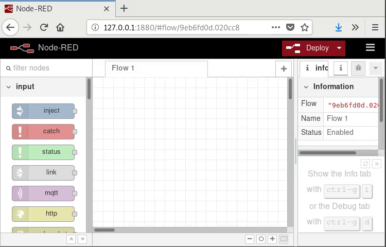
So what did just happen there?
First we start with the blank Node-RED interface.
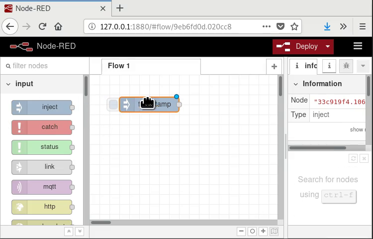
Then we drag the “inject” and “debug “nodes from the pool of available nodes into our flow window.
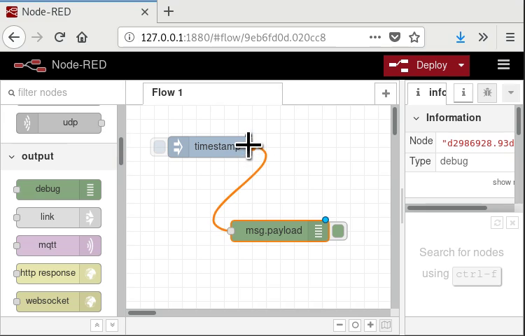
Next we connect the Nodes. That means whenever the “inject” node produces output it will go into the input of the “debug” node.
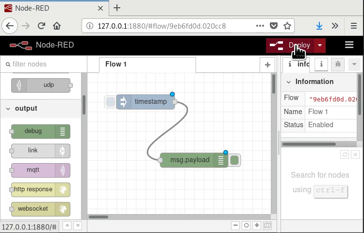
Next we start the flow…
… open the debug output…
… and trigger the inject node.
The inject node sends, via the connection we made, a message to the debug node and the debug node prints that message to the debug output window.
Node-RED and MQTT
The video below shows you how to connect Node-RED to the MQTT broker running on the Raspberry Pi:
Task: Try replicating the steps seen in the video.
Okay, once again: what did just happen there?
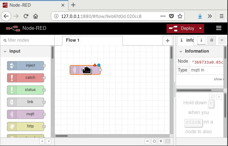
First we start with an empty flow and add an MQTT subscription node.
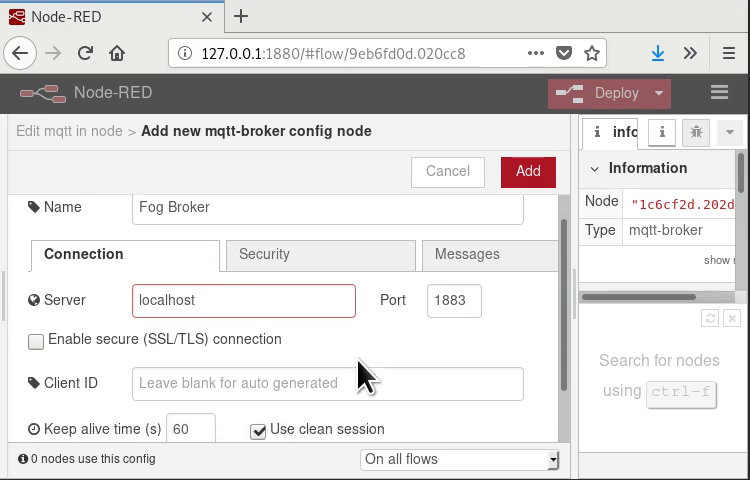
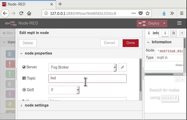
Next we set up the MQTT broker configuration
to connect to the broker running on localhost:1883.
Then we configure the node to subscribe to the /led
topic.
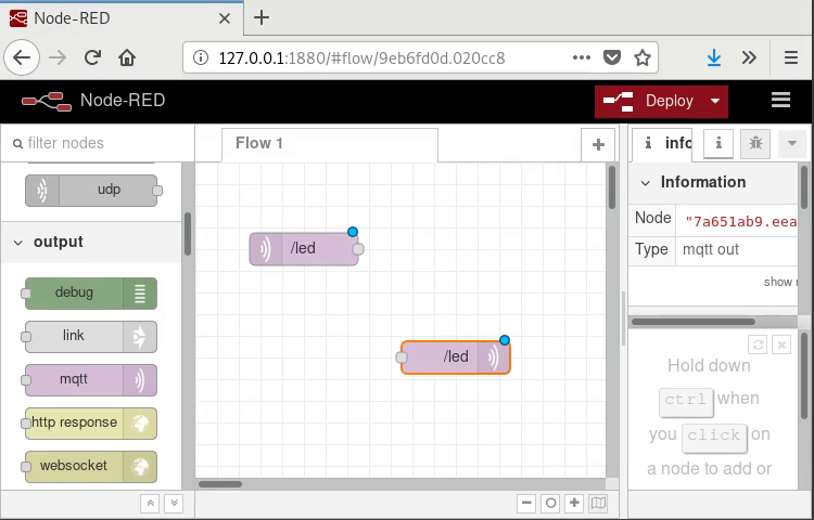
Next we set up an MQTT publish node to use the same
broker and to publish to the /led topic.
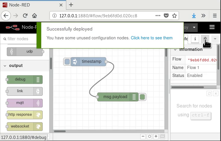
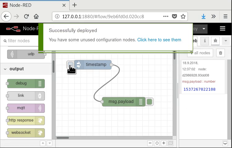
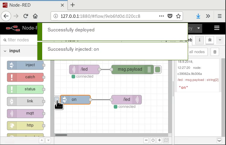
Finally we add a debug output node and an injection node.
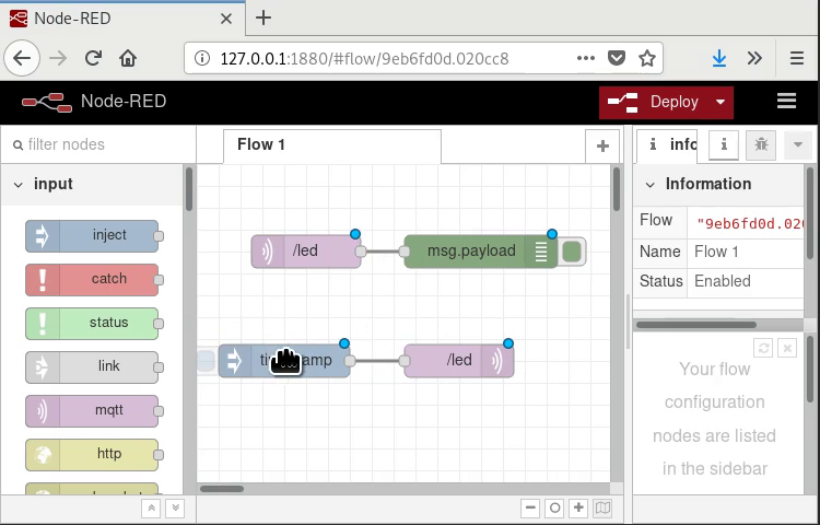
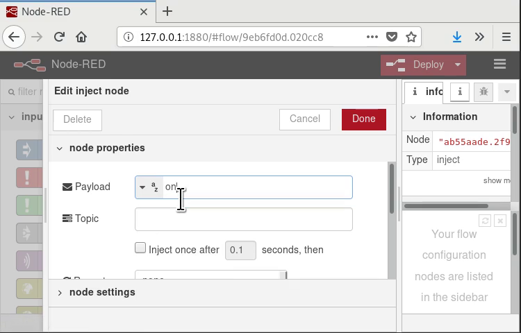
The inject node will, by default, inject a timestamp
message, we configure it to instead publish the
string on whenever it is triggered.
The image below shows the flow in action: the injected message is sent to the broker, received by the subscription node and displayed by the debug node.
Now that we know how to use Node-RED with MQTT we can make it actually do something.
Task: Add an injection node that injects the
string off.
Task: Connect the microcontrollers that you programmed in the last chapter and controll the LEDs from Node-RED.
Later on we want to make our setup more flexible by routing all the messages through Node-RED.
Right now we will prepare that step by decoupling the functionality of the publishing microcontroller and the subscribing microcontroller.
Task: Edit the program on the publishing
microcontroller to publish to the topic
/button instead of the topic /led.
The publishing microcontroller should now no longer be able to controll the LED.
Task: In Node-RED: subscribe to the /button
topic and, using a debug node, make sure that
messages are correctly received there.
Task: In Node-RED: forward messages from the
/button topic to the /led topic so that
the publishing microcontroller can
control the LED again.
Fog computing scenario
In this subchapter we will move the processing from our sensor and actuator nodes to the Raspberry Pi, acting as our fog node.
To do so we will use custom functions, written in javascipt, in Node-RED.
The Video below gives you an overview of how a function node is added to Node-RED.
This is the code snipped pasted into the function block 45 seconds into the video:
var led_status= context.get('led_status');

if (led_status === undefined) {
    led_status = 'off';
}

if (msg.payload === 'toggle') {
    if (led_status === 'on') {
        led_status = 'off';
    }
    else {
        led_status = 'on';
    }
}

context.set('led_status', led_status);

var out = {'payload': led_status};

return out;
Task: Recreate the flow shown in the video and, by reading the sourcecode and analyzing the behaviour, find out what the function node does.
Task: Change the function block so that, in addition to the
toggle functionality, injecting on and off messages
sets the LED state to on and off, regardless of previous state.
Now we want to integrate the function block into our hardware setup.
Task: Edit the program on your publishing microcontroller to
send pressed to the /button topic whenever the button
input goes from unpressed to pressed.
Task: Edit the function block in Node-RED to toggle the
LED state when the string pressed is received instead of
toggle.
Task: Add MQTT subscription and publishing nodes to the flow so that pressing the button on the publishing microcontroller toggles the LED on the subscribing microcontroller.
Task: Add a delay node to delay the reaction between pressing the button an changing the LED by two seconds.
TODO: Do more complicated stuff with, for example, delays or triggers.
TODO: Change publisher to read another sensor, like ultrasonic distance or temperature and publish measurements in a generic format like cm or °C.
TODO: Change subscriber to control another actuator than the LED and take commands in a generic format.
Cloud Computing
In this chapter we will have a look into the world of cloud computing.
HTTP
HTTP is an internet protocol on top of TCP that was initially designed to transfer websites over the internet.
Nowadays HTTP has become an ubiquitous protocol used in a lot of applications like, as we will see, IoT scenarios.
Before version 2.0 HTTP was a simple text
based protocol, so simple in fact that
will be manually sending an HTTP request to
a server using netcat.
Start netcat on the commandline and connect
to an HTTP server using the following command
(port 80 is the default port for unencrypted HTTP):
[user@computer ~]$ nc nota-cloud 80
Now enter the following text, making sure
to press the enter key whenever you see the
⏎ symbol:
GET / HTTP/1.1⏎
Host: nota-cloud⏎
⏎
The output should now look something like the following:
[user@computer ~]$ nc nota-cloud 80
GET / HTTP/1.1
Host: nota-cloud

HTTP/1.1 200 OK
Server: nginx/1.10.3
Date: Mon, 01 Jan 2018 00:00:01 GMT
Content-Type: text/html
Content-Length: 986
Last-Modified: Mon, 01 Jan 2018 00:00:00 GMT
Connection: keep-alive
ETag: "deadbeef-123"
Accept-Ranges: bytes

<html xmlns="http://www.w3.org/1999/xhtml">
<head>
  <meta http-equiv="Content-Type" content="text/html; charset=utf-8" />
  <meta http-equiv="Content-Style-Type" content="text/css" />
  <title>Unencrypted Nota Server content</title>
</head>
 <body>
  <h1>Unencrypted NoTA Server content</h1>
  <ul>
    <li><a href="https://nota-cloud/">Encrypted version</a></li>
    <li><a href="/nota-ca.crt">Certificate for encrypted page</a></li>
  </ul>
 </body>
</html>
In this output we can see most things we have to know about HTTP.
Request Header
The request header is the part we sent to the server:
GET / HTTP/1.1
Host: nota-cloud
It contains:
- The request method, in this case we want to
GETa ressource from the server, we could alsoPOSTressources to the server orDELETEressources if the server lets us. - The ressource path, in this case we want to
GETthe index/, we could also request other ressources likeressource.html. - The request header parameters, in this case just
the
Hostheader that tells the server which host we expect to talk to.
Request Body
When POSTing or PUTing ressources to the server
we want to include actual data in our request.
This would be sent after the request headers.
In this case we did not send any data to the server.
Response Header
The response header is the first part of the transfer sent by the server:
HTTP/1.1 200 OK
Server: nginx/1.10.3
Date: Mon, 01 Jan 2018 00:00:01 GMT
Content-Type: text/html
Content-Length: 986
Last-Modified: Mon, 01 Jan 2018 00:00:00 GMT
Connection: keep-alive
ETag: "deadbeef-123"
Accept-Ranges: bytes
The response header contains:
- The status code, in this case everything went
well and we got a
200 OKcode, other common codes are404 Not Foundor500 Internal Server Error. - The response header parameters, in this case
for example the
Serverparameter that tells us that the server software is callednginx.
Response Body
Everything following the response headers is part of the requested ressource, in this case a HTML page intened to be rendered by a web browser, containing links to other ressources.
HTTPS
Instead of bare TCP HTTP can also be used with an encrypted TLS layer on top of TCP, this is secure HTTP or HTTPS.
Using HTTPS instead of HTTP makes sure that no unauthorized user can impersonate the server and that the content of the transfer can not be intercepted by third parties.
Nowadays unencrypted communication like HTTP over the public internet is only used in legacy setups and is highly discouraged.
Do not run unencrypted services over the public internet!
Do not run unencrypted services over the public internet!
Do not run unencrypted services over the public internet!
REST
In this lab we will be using REST over HTTPS to send data to our cloud server.
In REST we use the appropriate HTTP method to transfer state from and to the server.
The most important methods are:
GETto get ressources from the server.DELETEto delete a ressource on the server.POSTto create a new ressource on the server.PUTto replace a ressource with a new one.
We will now manually use some of these methods to exchange information with the cloud server.
But first we will find the name of your
device as we will use it to identify us later
on. Execute the command below and remember its
output, it will be something like nota-1 or nota-2.
[user@computer ~]$ uname -n
nota-x
Now open the cloud application in a new tab, when you successfully send data later on you should see it appear there (although you may have to refresh the page).
POST
First we will send a new ressource to the server
using the POST method.
Replace the nota-x part in the URL below by the
name of your device, as found out before.
[user@computer ~]$ http -v POST https://nota-cloud/api/log/nota-x value:=1
Task: Execute the command multiple times with different values and observe the cloud application.
GET
Next we want to get back the information sent to the
server using the GET method.
First we request a list of device names that sent data to the server:
[user@computer ~]$  http -v GET https://nota-cloud/api/log
GET /api/log HTTP/1.1
Accept: */*
Accept-Encoding: gzip, deflate
Connection: keep-alive
Host: nota-cloud
User-Agent: HTTPie/0.9.8


HTTP/1.1 200 OK
Access-Control-Allow-Origin: *
Connection: keep-alive
Content-Length: 40
Content-Type: application/json
Date: Mon, 01 Jan 2018 00:00:00 GMT
Server: nginx/1.10.3
Strict-Transport-Security: max-age=15768000

{
    "keys": [
        "nota-1",
        "nota-2",
        "nota-3"
    ]
}
We can see that the nota-1, nota-2 and
nota-3 ressources exist on the server.
Next we can request one of these ressources from the server:
[user@computer ~]$ http -v GET https://nota-cloud/api/log/nota-1
GET /api/log/nota-1 HTTP/1.1
Accept: */*
Accept-Encoding: gzip, deflate
Connection: keep-alive
Host: nota-cloud
User-Agent: HTTPie/0.9.8


HTTP/1.1 200 OK
Access-Control-Allow-Origin: *
Connection: keep-alive
Content-Length: 5343
Content-Type: application/json
Date: Mon, 1 Jan 2018 00:00:00 GMT
Server: nginx/1.10.3
Strict-Transport-Security: max-age=15768000

{
    "values": [
        {
            "timestamp": 1500000000.000000,
            "value": 1.0
        },
        {
            "timestamp": 1500000001.000000,
            "value": 2.0
        },
        …
    ]
}
Note: we did not perform any authentication
of the user, for example using an username and password,
so anyone can POST and GET data to and from the server.
This was done as a simplificiation in the lab
and is obviously bad practice.
Do not run unauthenticated services over the public internet!
JSON
In the response header we can see
a Content-Type: application/json line
that specifies the file type of the
response body to be JSON.
JSON is a common internet data format based on the way JavaScript represents data objects.
In the response above we see the main JSON components.
- Collections of name/value pairs:
{"name_1": "value_1", "name_2: "value_2"} - Numbered collections:
["value_1", "value_2", "value_3"] - Strings:
"text" - Numbers:
1.0
Names in collections are always strings, values can be any other type, even other collections allowing for nested structures.
How entries in a JSON file are represented and accessed depends on the programming language and library used but the following pseudo-code interaction should give you an intuition:
> var json_file = {
>    "values": [
>        { "timestamp": 1500000000.000000, "value": 1.0 },
>        { "timestamp": 1500000001.000000, "value": 2.0 }
>    ]
> };

> json_file["values"]
[
   { "timestamp": 1500000000.000000, "value": 1.0 },
   { "timestamp": 1500000001.000000, "value": 2.0 }
]

> json_file["values"][0]
{ "timestamp": 1500000000.000000, "value": 1.0 }

> json_file["values"][0]["timestamp"]
1500000000.000000
Fog to Cloud
In this subchapter we will link out Node-RED based Fog setup to an existing cloud application using HTTPS, REST and JSON.
First we will generate a Node-RED flow that produces appropriately formatted JSON objects and then we will send these fragments to the cloud application.
Generating Data
First we will need to generate data to send to the cloud application.
Task: Based on the “Fog Scenario” subchapter write a function block that behaves like in the video below. The node should output a number that increments whenever a message with the payload “pressed” is received.
Generating JSON
Next we will want a node that formats the data in a format suitable for the cloud application.
The following code, when placed in a function block, does just that:
var obj = {'value' : msg.payload};
var out = {'payload' : obj};

return out;
The output is of the format {'value': 1},
ready to be sent to the cloud application.
Sending HTTP Requests
The video below shows you how to setup Node-RED to send
an HTTP POST request to the https://nota-cloud/api/log/nota-1
endpoint whenever a button press event is received.
Task: Add an HTTP request block to your flow. Set the endpoint address to the one corresponding to you device name.
Cloud Scenario
Finally we want to also receive data
from the cloud, to do so we will use
HTTP GET requests.
We will create a new Node-RED flow that periodically sends request to the server and acts on the received data.
The video above uses an inject node that sends an empty message every five seconds to trigger a request to the server.
The response is then formatted using function block containing the following code:
var values = msg.payload['values'];
var last = values[values.length - 1];
var value = last['value'];

var out = { 'payload' : value };

return out;
Task: Replicate the flow setup shown in the video. Replace the endpoint configured in the http request node by the one corresponding to your device name.
Task: By reading the sourcecode and experimenting find out what the flow does and what the output of the “Formatter” function node is.
Task: Control a microcontroller based on the output of the “Formatter” block. E.g. turn on a light after a certain number of button presses.
Group phase
Step 1: Choose a sensor you would like to use and, using the microcontroller, MQTT, Node-RED and HTTP build a complete chain to send sensor readings to the cloud.
Step 2: Fetch sensor readings from another group from the cloud and control an actuator of your liking based on the values you get.
Example: One group builds a thermometer that publishes temperatures to the cloud. You take the readings from that sensor and, once it gets too hot, use a servo motor and a piece of paper to fan air.
Epilogue
This was it, the Network-of-Things Engineering (Nota) Lab, we hope you enjoyed it and may have even learned something.
Everything about the Nota Lab is free and open source and you are encouraged to participate in its development.
If you would like doing so you may meet us on the Nota Lab project page.