WiFi

Connecting Arduinos to the internet

ESP8266

To connect the Arduinos to a WiFi network we will be using ESP8266 shields

We will be using AT commands to control the ESPs

The ESP8266 chips could also be programmed directly as they contain a microcontroller that is much more powerful than the Arduino

Do not reflash the ESP shields provided in the course

Testing the shields

Testing

To check if your shield is working correctly disconnect the USB-cable from your Arduino

1 esp_client.begin(
2     &esp_serial, "GDI", "password",
3     "192.168.42.42", 30303
4 );

and copy this program into the Arduino IDE, scroll down to the setup function and adapt the IP address to one provided by your tutor

Testing

Connect the RGB-Led to the pins on the WiFi-shield that will be plugged into the following Arduino pins:

R - 9 / G - 10 / B - 11 / GND - GND

Carefully plug the WiFi-shield into your Arduino and reconnect the USB-cable

Testing

1 self.coro= aio.start_server(
2     self.handle_client,
3     None,
4     30303,
5     loop= self.loop
6 )

Your Tutor is running this program, it provides a TCP-server for your Arduino to connect to

It then sends periodic color updates to every Arduino connected

The test code on the previous slides used a python server and an Arduino client

Arduino ---connects to--> Python

To prevent issues with firewalls and NATs from now on the Arduino will act as a server and the python code will connect to it

Python ---connects to--> Arduino

The following slides will provide you with an Arduino library to use the WiFi shield as a Server

The library allows exactly one connection and does not perform any error checking, this is why it is called DumbServer

DumbServer.cpp

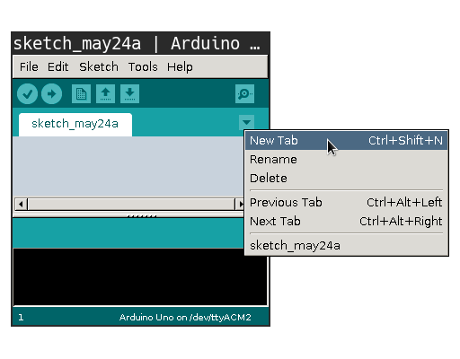
Arduino new Tab

Use the "New Tab" option in the Arduino IDE to create the files DumbServer.h and DumbServer.cpp

Paste the contents of DumbServer.h / DumbServer.cpp into the respective files

Paste the content of ServerExample.ino into the main sketch file

DumbServer.cpp

Flash the sketch to your Arduino and open the Serial Monitor

Starting server...

...server is running

My ip: 192.168.42.123

If the ESP was able to connect to the WiFi access point the Serial Monitor should display a message like the one above

We will be needing the IP-address that is shown later on

socket.py

Open an interactive python session and enter the following commands

Replace the IP-address with the one found previously

1 import socket
2 
3 s= socket.socket()
4 s.connect(('192.168.42.123', 30303))
5 s.setblocking(False)
6 
7 s.send(b'Hello World\n')
8 
9 s.recv(1024)

Check if the observed behaviour matches the Arduino sketch

On the following slides you will see an example on how to work with sockets in a graphical program

sockets & GUIs

1 while(esp_server.available()) {
2     String command= esp_server.readStringUntil('\n');
3     digitalWrite(13, (command == "on") ? HIGH : LOW);
4 }

Flash the code above onto your Arduino

Connect Arduino pin 13 to an LED and pin 12 to GND

Note: DumbServer.h/.cpp are needed to compile the program

sockets & GUIs

Light Center

$ python3 22_light_center.py
Hostname: 192.168.42.123
Port: 30303

Run the GUI code and provide it with the correct IP-address